
需求描述
基于寄存器操作,使用SPI功能,完成Flash的读写。
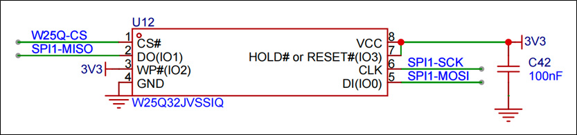
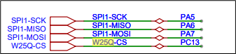
硬件电路设计
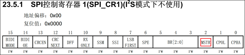
使用到的寄存器
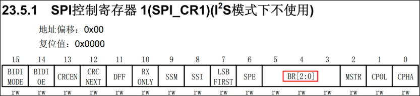
配置SPI模式
代码
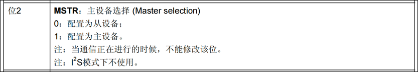
 /* 3.1 配置主模式 0=从设备 1=主设备*/
SPI1->CR1 |= SPI_CR1_MSTR;
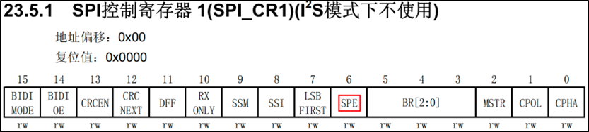
寄存器
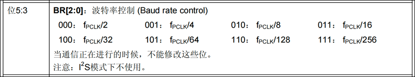
SPI波特率控制
代码
 /* 3.2 选择分频系数 000=fpclk/2, 001=fpclk/4 ....,我们选择4分频  */
SPI1->CR1 &= ~SPI_CR1_BR;
SPI1->CR1 |= SPI_CR1_BR_0;
寄存器
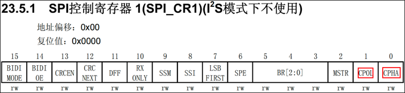
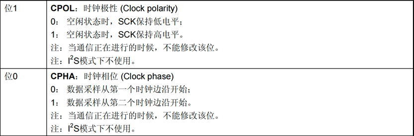
时钟的极性和相位
代码
/* 3.3 时钟极性 0: 空闲状态时,SCK保持低电平;1: 空闲状态时,SCK保持高电平。 */
SPI1->CR1 &= ~SPI_CR1_CPOL;
/* 3.4 时钟相位  0: 数据采样从第一个时钟边沿开始;1: 数据采样从第二个时钟边沿开始。*/
SPI1->CR1 &= ~SPI_CR1_CPHA;
寄存器
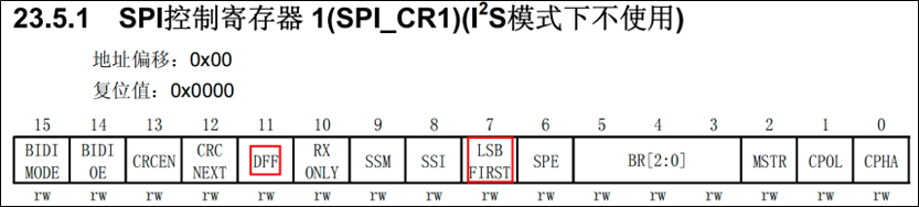
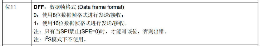
数据帧格式和传输顺序
代码
/* 3.5 数据帧格式 0:8位数据帧;1:16位数据帧 */
SPI1->CR1 &= ~SPI_CR1_DFF;
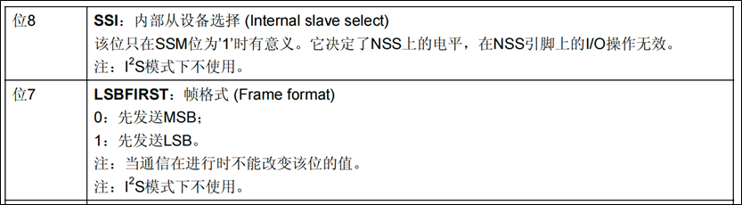
/* 3.6 数据传输顺序 0:先发送MSB;1:先发送LSB。 */
SPI1->CR1 &= ~SPI_CR1_LSBFIRST; /* 高位先行 */
寄存器
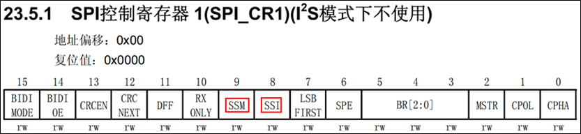
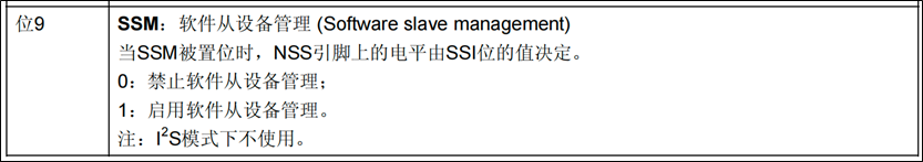
配置片选方式
代码
/* 3.7 使用软件实现片选(我们自己控制CS)0:禁止软件从设备管理;1:启用软件从设备管理。 */
SPI1->CR1 |= SPI_CR1_SSM;
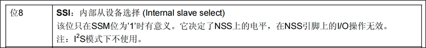
/* 3.8 当SSM=0时,这个时候对SSI的操作无效,必须设置为1 */
SPI1->CR1 |= SPI_CR1_SSI;
寄存器
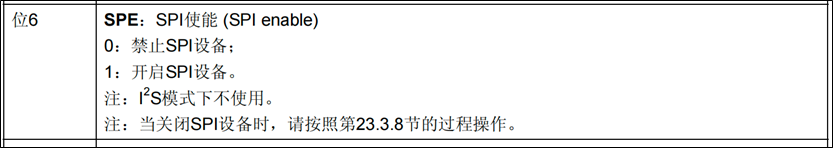
启动SPI
代码
/* 4 启动SPI1 0:禁止SPI设备;1:开启SPI设备。*/
SPI1->CR1 |= SPI_CR1_SPE;
寄存器
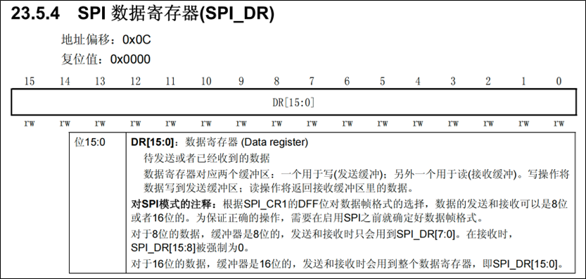
SPI读写数据
代码
uint8_t SPI_SwapByte(uint8_t byte_sended)
{
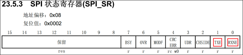
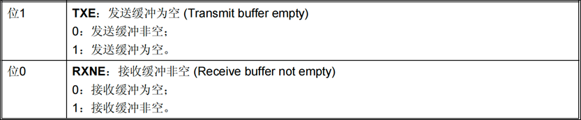
/* 1. 等待发送缓冲区为空 */
while (!(SPI1->SR & SPI_SR_TXE))
;
/* 2. 把数据写入到数据寄存器 */
SPI1->DR = byte_sended;
/* 3. 等待接收缓冲区非空 */
while (!(SPI1->SR & SPI_SR_RXNE))
;
/* 4. 返回读到的字节数据 */
return SPI1->DR;
}
寄存器
寄存器实现
w25q32.h
#ifndef __W25Q32_H
#define __W25Q32_H

#include "spi.h"

// 初始化
void W25Q32_Init(void);

// 读取ID
void W25Q32_ReadID(uint8_t * mid, uint16_t * did);

// 开启写使能
void W25Q32_WriteEnable(void);

// 关闭写使能
void W25Q32_WriteDisable(void);

// 等待状态不为忙(busy)
void W25Q32_WaitNotBusy(void);

// 擦除段(sector erase),地址只需要块号和段号
void W25Q32_EraseSector(uint8_t block, uint8_t sector);

// 写入(页写)
void W25Q32_PageWrite(uint8_t block, uint8_t sector, uint8_t page, uint8_t * data, uint16_t len);

// 读取
void W25Q32_Read(uint8_t block, uint8_t sector, uint8_t page, uint8_t innerAddr, uint8_t * buffer, uint16_t len);

#endif
w25q32.c
#include "w25q32.h"

// 初始化
void W25Q32_Init(void)
{
    SPI_Init();
}

// 读取ID
void W25Q32_ReadID(uint8_t *mid, uint16_t *did)
{
    SPI_Start();

    // 1. 发送指令 9fh
    SPI_SwapByte(0x9f);

    // 2. 获取制造商ID(为了读取数据,发送什么不重要)
    *mid = SPI_SwapByte(0xff);

    // 3. 获取设备ID
    *did = 0;
    *did |= SPI_SwapByte(0xff) << 8;
    *did |= SPI_SwapByte(0xff) & 0xff;

    SPI_Stop();
}

// 开启写使能
void W25Q32_WriteEnable(void)
{
    SPI_Start();
    SPI_SwapByte(0x06);
    SPI_Stop();
}

// 关闭写使能
void W25Q32_WriteDisable(void)
{
    SPI_Start();
    SPI_SwapByte(0x04);
    SPI_Stop();
}

// 等待状态不为忙(busy)
void W25Q32_WaitNotBusy(void)
{
    SPI_Start();

    // 发送读取状态寄存器指令
    SPI_SwapByte(0x05);

    // 等待收到的数据末位变成0
    while (SPI_SwapByte(0xff) & 0x01)
    {
    }

    SPI_Stop();
}

// 擦除段(sector erase),地址只需要块号和段号
void W25Q32_EraseSector(uint8_t block, uint8_t sector)
{
    // 首先等待状态不为忙
    W25Q32_WaitNotBusy();

    // 开启写使能
    W25Q32_WriteEnable();

    // 计算要发送的地址(段首地址)
    uint32_t addr = (block << 16) + (sector << 12);

    SPI_Start();

    // 发送指令
    SPI_SwapByte(0x20);

    SPI_SwapByte(addr >> 16 & 0xff); // 第一个字节
    SPI_SwapByte(addr >> 8 & 0xff);  // 第二个字节
    SPI_SwapByte(addr >> 0 & 0xff);  // 第三个字节

    SPI_Stop();

    W25Q32_WriteDisable();
}

// 写入(页写)
void W25Q32_PageWrite(uint8_t block, uint8_t sector, uint8_t page, uint8_t *data, uint16_t len)
{
    // 首先等待状态不为忙
    W25Q32_WaitNotBusy();

    // 开启写使能
    W25Q32_WriteEnable();

    // 计算要发送的地址(页首地址)
    uint32_t addr = (block << 16) + (sector << 12) + (page << 8);

    SPI_Start();

    // 发送指令
    SPI_SwapByte(0x02);

    // 发送24位地址
    SPI_SwapByte(addr >> 16); // 第一个字节
    SPI_SwapByte(addr >> 8);  // 第二个字节
    SPI_SwapByte(addr >> 0);  // 第三个字节

    //  依次发送数据
    for (uint16_t i = 0; i < len; i++)
    {
        SPI_SwapByte(data[i]);
    }

    SPI_Stop();

    W25Q32_WriteDisable();
}

// 读取
void W25Q32_Read(uint8_t block, uint8_t sector, uint8_t page, uint8_t innerAddr, uint8_t *buffer, uint16_t len)
{
    // 首先等待状态不为忙
    W25Q32_WaitNotBusy();

    // 计算要发送的地址
    uint32_t addr = (block << 16) + (sector << 12) + (page << 8) + innerAddr;

    SPI_Start();

    // 发送指令
    SPI_SwapByte(0x03);

    // 发送24位地址
    SPI_SwapByte(addr >> 16 & 0xff); // 第一个字节
    SPI_SwapByte(addr >> 8 & 0xff);  // 第二个字节
    SPI_SwapByte(addr >> 0 & 0xff);  // 第三个字节

    //  依次读取数据
    for (uint16_t i = 0; i < len; i++)
    {
        buffer[i] = SPI_SwapByte(0xff);
    }

    SPI_Stop();
}
spi.h
#ifndef __SPI_H
#define __SPI_H

#include "stm32f10x.h"

// 宏定义,不同引脚输出高低电平
#define CS_HIGH (GPIOC->ODR |= GPIO_ODR_ODR13)
#define CS_LOW (GPIOC->ODR &= ~GPIO_ODR_ODR13)

// 初始化
void SPI_Init(void);

// 数据传输的开始和结束
void SPI_Start(void);
void SPI_Stop(void);

// 主从设备交换一个字节的数据
uint8_t SPI_SwapByte(uint8_t byte);

#endif
spi.c
#include "spi.h"

// 初始化
void SPI_Init(void)
{
    // 1. 开启时钟
    RCC->APB2ENR |= RCC_APB2ENR_IOPAEN;
    RCC->APB2ENR |= RCC_APB2ENR_IOPCEN;
    RCC->APB2ENR |= RCC_APB2ENR_SPI1EN;

    // 2. GPIO工作模式
    // PC13:通用推挽输出,CNF = 00,MODE = 11
    GPIOC->CRH |= GPIO_CRH_MODE13;
    GPIOC->CRH &= ~GPIO_CRH_CNF13;

    // PA5、PA7: 复用推挽输出,CNF = 10,MODE = 11
    GPIOA->CRL |= GPIO_CRL_MODE5;
    GPIOA->CRL |= GPIO_CRL_CNF5_1;
    GPIOA->CRL &= ~GPIO_CRL_CNF5_0;

    GPIOA->CRL |= GPIO_CRL_MODE7;
    GPIOA->CRL |= GPIO_CRL_CNF7_1;
    GPIOA->CRL &= ~GPIO_CRL_CNF7_0;

    // PA6:MISO,浮空输入,CNF = 01,MODE = 00
    GPIOA->CRL &= ~GPIO_CRL_MODE6;
    GPIOA->CRL &= ~GPIO_CRL_CNF6_1;
    GPIOA->CRL |= GPIO_CRL_CNF6_0;

    // 3. SPI相关配置
    // 3.1 配置SPI为主模式
    SPI1->CR1 |= SPI_CR1_MSTR;

    // 3.2 使用软件控制片选信号,直接拉高
    SPI1->CR1 |= SPI_CR1_SSM;
    SPI1->CR1 |= SPI_CR1_SSI;

    // 3.3 配置工作模式0,时钟极性和相位
    SPI1->CR1 &= ~SPI_CR1_CPOL;
    SPI1->CR1 &= ~SPI_CR1_CPHA;

    // 3.4 配置时钟分频系数,波特率选择:BR-001
    SPI1->CR1 &= ~SPI_CR1_BR;
    SPI1->CR1 |= SPI_CR1_BR_0;

    // 3.5 设置数据帧格式
    SPI1->CR1 &= ~SPI_CR1_DFF;

    // 3.6 配置高位先行MSB
    SPI1->CR1 &= ~SPI_CR1_LSBFIRST;

    // 3.7 SPI模块使能
    SPI1->CR1 |= SPI_CR1_SPE;
}

// 数据传输的开始和结束
void SPI_Start(void)
{
    CS_LOW;
}
void SPI_Stop(void)
{
    CS_HIGH;
}

// 主从设备交换一个字节的数据
uint8_t SPI_SwapByte(uint8_t byte)
{
    // 1. 将要发送的数据byte写入发送缓冲区
    // 1.1 等待发送缓冲区为空
    while ((SPI1->SR & SPI_SR_TXE) == 0)
    {}

    // 1.2 将数据byte写入DR寄存器
    SPI1->DR = byte;

    // 2. 读取MISO发来的数据
    // 2.1 等待接收缓冲区为非空
    while ((SPI1->SR & SPI_SR_RXNE) == 0)
    {}
    // 2.1 从接收缓冲区读取数据,返回
    return (uint8_t)(SPI1->DR & 0xff);
}
main.c
#include "usart.h"
#include "w25q32.h"
#include <string.h>

int main(void)
{
	// 1. 初始化
	USART_Init();
	W25Q32_Init();

	printf("尚硅谷SPI软件模拟实验开始...\n");

	// 2. 读取ID进行测试
	uint8_t mid = 0;
	uint16_t did = 0;
	W25Q32_ReadID(&mid, &did);
	printf("mid = %#x, did = %#x\n", mid, did);

	// 3. 段擦除
	W25Q32_EraseSector(0, 0);

	// 4. 页写
	W25Q32_PageWrite(0, 0, 0, "12345678", 8);

	// 5. 读取
	uint8_t buffer[10] = {0};
	W25Q32_Read(0, 0, 0, 2, buffer, 6);

	printf("buffer = %s\n", buffer);

	while (1)
	{
	}
}
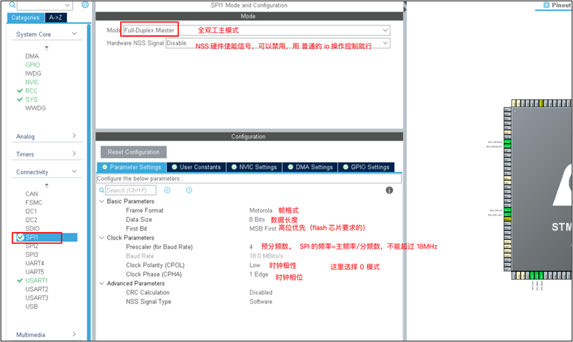
HAL库实现
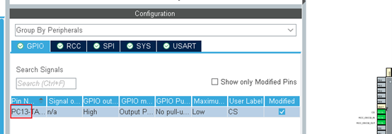
HAL库设置
添加的其他代码
main.c
int main(void)
{

    HAL_Init();
    SystemClock_Config();
    MX_GPIO_Init();
    MX_SPI1_Init();
    MX_USART1_UART_Init();
    /* 读取id测试是否正常 */
    uint8_t mid = 0;
    uint16_t did = 0;
    Inf_W25Q32_ReadId(&mid, &did);
    printf("mid=0x%X, did=0x%X\r\n", mid, did);

    /* 先擦除 */;
    Inf_W25Q32_EraseSector(0, 0);
    Inf_W25Q32_EraseSector(0, 1);

    Inf_W25Q32_WritePage(0, 0, 0, "abc", 3);
    Inf_W25Q32_WritePage(0, 1, 0, "456", 3);
    uint8_t buff[10] = {0};
    Inf_W25Q32_Read(0, 0, 0, buff, 3);
    printf("%s\r\n", buff);
    Inf_W25Q32_Read(0, 1, 0, buff, 3);
    printf("%s\r\n", buff);
    while (1)
    {
    }
}
spi.h
/* USER CODE BEGIN 2 */

  printf("SPI软件模拟实验开始...\n");

  // 2. 读取ID进行测试
  uint8_t mid = 0;
  uint16_t did = 0;
  W25Q32_ReadID(&mid, &did);
  printf("mid = %#x, did = %#x\n", mid, did);

  // 3. 段擦除
  W25Q32_EraseSector(0, 0);

  // 4. 页写
  W25Q32_PageWrite(0, 0, 0, "12345678", 8);

  // 5. 读取
  uint8_t buffer[10] = {0};
  W25Q32_Read(0, 0, 0, 2, buffer, 6);

  printf("buffer = %s\n", buffer);

  /* USER CODE END 2 */
spi.c
/* USER CODE BEGIN Prototypes */
void SPI_Start(void);
void SPI_Stop(void);

uint8_t SPI_SwapByte(uint8_t byte);
/* USER CODE END Prototypes */
w25q32.h
#ifndef __W25Q32_H
#define __W25Q32_H

#include "spi.h"

// 初始化
void W25Q32_Init(void);

// 读取ID
void W25Q32_ReadID(uint8_t * mid, uint16_t * did);

// 开启写使能
void W25Q32_WriteEnable(void);

// 关闭写使能
void W25Q32_WriteDisable(void);

// 等待状态不为忙(busy)
void W25Q32_WaitNotBusy(void);

// 擦除段(sector erase),地址只需要块号和段号
void W25Q32_EraseSector(uint8_t block, uint8_t sector);

// 写入(页写)
void W25Q32_PageWrite(uint8_t block, uint8_t sector, uint8_t page, uint8_t * data, uint16_t len);

// 读取
void W25Q32_Read(uint8_t block, uint8_t sector, uint8_t page, uint8_t innerAddr, uint8_t * buffer, uint16_t len);

#endif
w25q32.c
#include "w25q32.h"

// 初始化
void W25Q32_Init(void)
{
    MX_SPI1_Init();
}

// 读取ID
void W25Q32_ReadID(uint8_t *mid, uint16_t *did)
{
    SPI_Start();

    // 1. 发送指令 9fh
    SPI_SwapByte(0x9f);

    // 2. 获取制造商ID(为了读取数据,发送什么不重要)
    *mid = SPI_SwapByte(0xff);

    // 3. 获取设备ID
    *did = 0;
    *did |= SPI_SwapByte(0xff) << 8;
    *did |= SPI_SwapByte(0xff) & 0xff;

    SPI_Stop();
}

// 开启写使能
void W25Q32_WriteEnable(void)
{
    SPI_Start();
    SPI_SwapByte(0x06);
    SPI_Stop();
}

// 关闭写使能
void W25Q32_WriteDisable(void)
{
    SPI_Start();
    SPI_SwapByte(0x04);
    SPI_Stop();
}

// 等待状态不为忙(busy)
void W25Q32_WaitNotBusy(void)
{
    SPI_Start();

    // 发送读取状态寄存器指令
    SPI_SwapByte(0x05);

    // 等待收到的数据末位变成0
    while (SPI_SwapByte(0xff) & 0x01)
    {
    }

    SPI_Stop();
}

// 擦除段(sector erase),地址只需要块号和段号
void W25Q32_EraseSector(uint8_t block, uint8_t sector)
{
    // 首先等待状态不为忙
    W25Q32_WaitNotBusy();

    // 开启写使能
    W25Q32_WriteEnable();

    // 计算要发送的地址(段首地址)
    uint32_t addr = (block << 16) + (sector << 12);

    SPI_Start();

    // 发送指令
    SPI_SwapByte(0x20);

    SPI_SwapByte(addr >> 16 & 0xff); // 第一个字节
    SPI_SwapByte(addr >> 8 & 0xff);  // 第二个字节
    SPI_SwapByte(addr >> 0 & 0xff);  // 第三个字节

    SPI_Stop();

    W25Q32_WriteDisable();
}

// 写入(页写)
void W25Q32_PageWrite(uint8_t block, uint8_t sector, uint8_t page, uint8_t *data, uint16_t len)
{
    // 首先等待状态不为忙
    W25Q32_WaitNotBusy();

    // 开启写使能
    W25Q32_WriteEnable();

    // 计算要发送的地址(页首地址)
    uint32_t addr = (block << 16) + (sector << 12) + (page << 8);

    SPI_Start();

    // 发送指令
    SPI_SwapByte(0x02);

    // 发送24位地址
    SPI_SwapByte(addr >> 16); // 第一个字节
    SPI_SwapByte(addr >> 8);  // 第二个字节
    SPI_SwapByte(addr >> 0);  // 第三个字节

    //  依次发送数据
    for (uint16_t i = 0; i < len; i++)
    {
        SPI_SwapByte(data[i]);
    }

    SPI_Stop();

    W25Q32_WriteDisable();
}

// 读取
void W25Q32_Read(uint8_t block, uint8_t sector, uint8_t page, uint8_t innerAddr, uint8_t *buffer, uint16_t len)
{
    // 首先等待状态不为忙
    W25Q32_WaitNotBusy();

    // 计算要发送的地址
    uint32_t addr = (block << 16) + (sector << 12) + (page << 8) + innerAddr;

    SPI_Start();

    // 发送指令
    SPI_SwapByte(0x03);

    // 发送24位地址
    SPI_SwapByte(addr >> 16 & 0xff); // 第一个字节
    SPI_SwapByte(addr >> 8 & 0xff);  // 第二个字节
    SPI_SwapByte(addr >> 0 & 0xff);  // 第三个字节

    //  依次读取数据
    for (uint16_t i = 0; i < len; i++)
    {
        buffer[i] = SPI_SwapByte(0xff);
    }

    SPI_Stop();
}